RFID door lock project
Hardware | Software
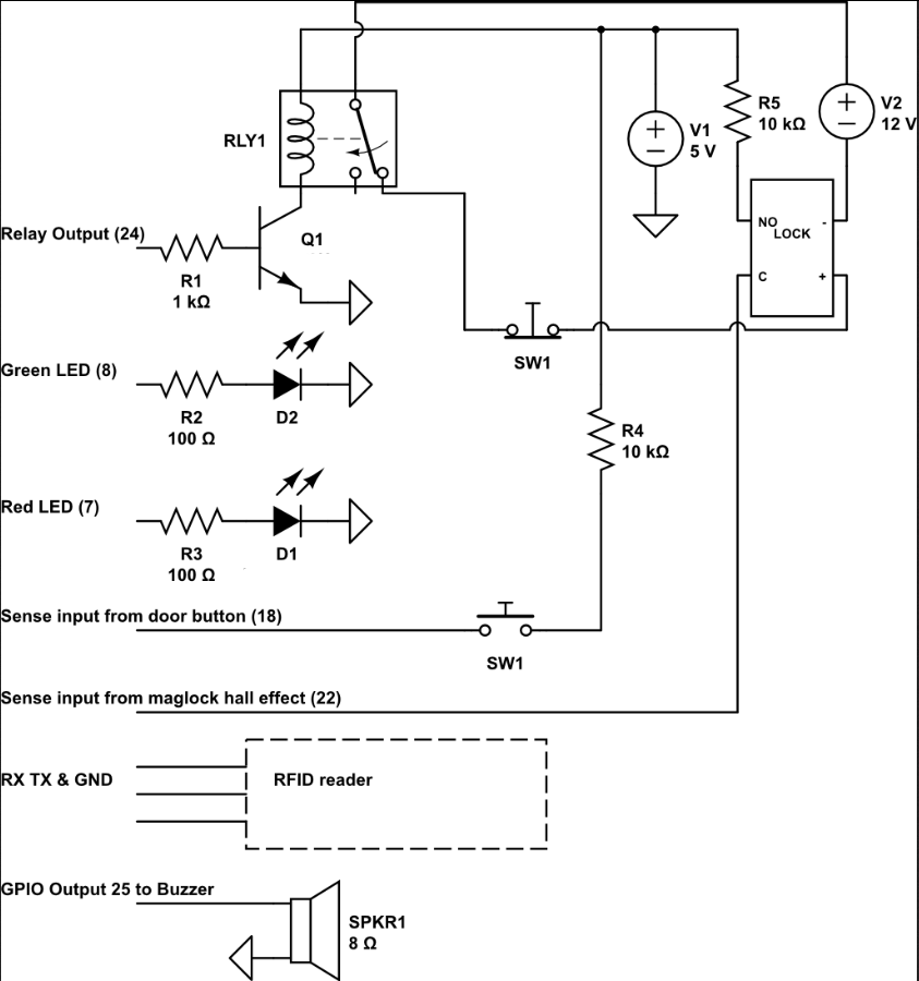
Making the interface board
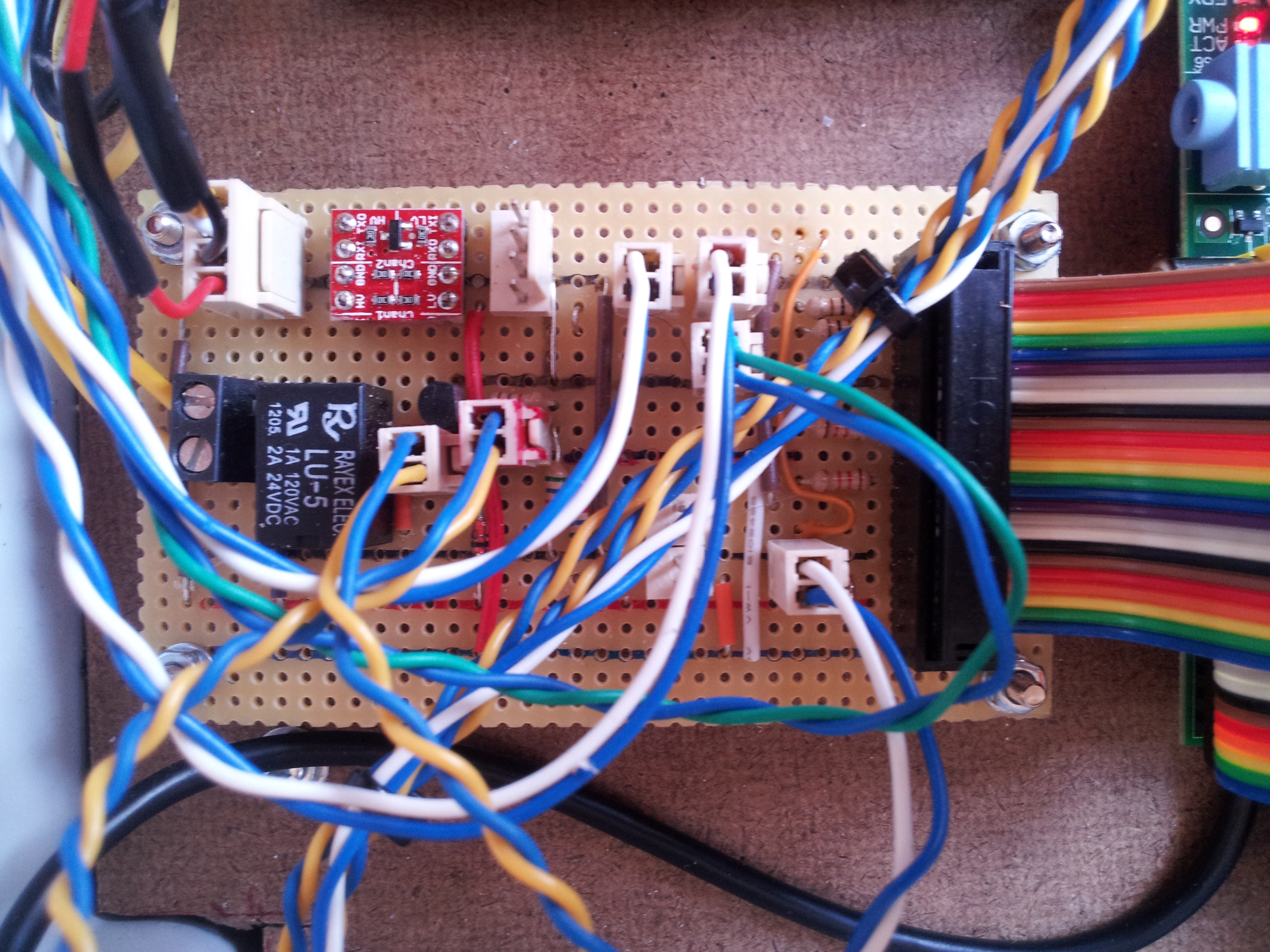
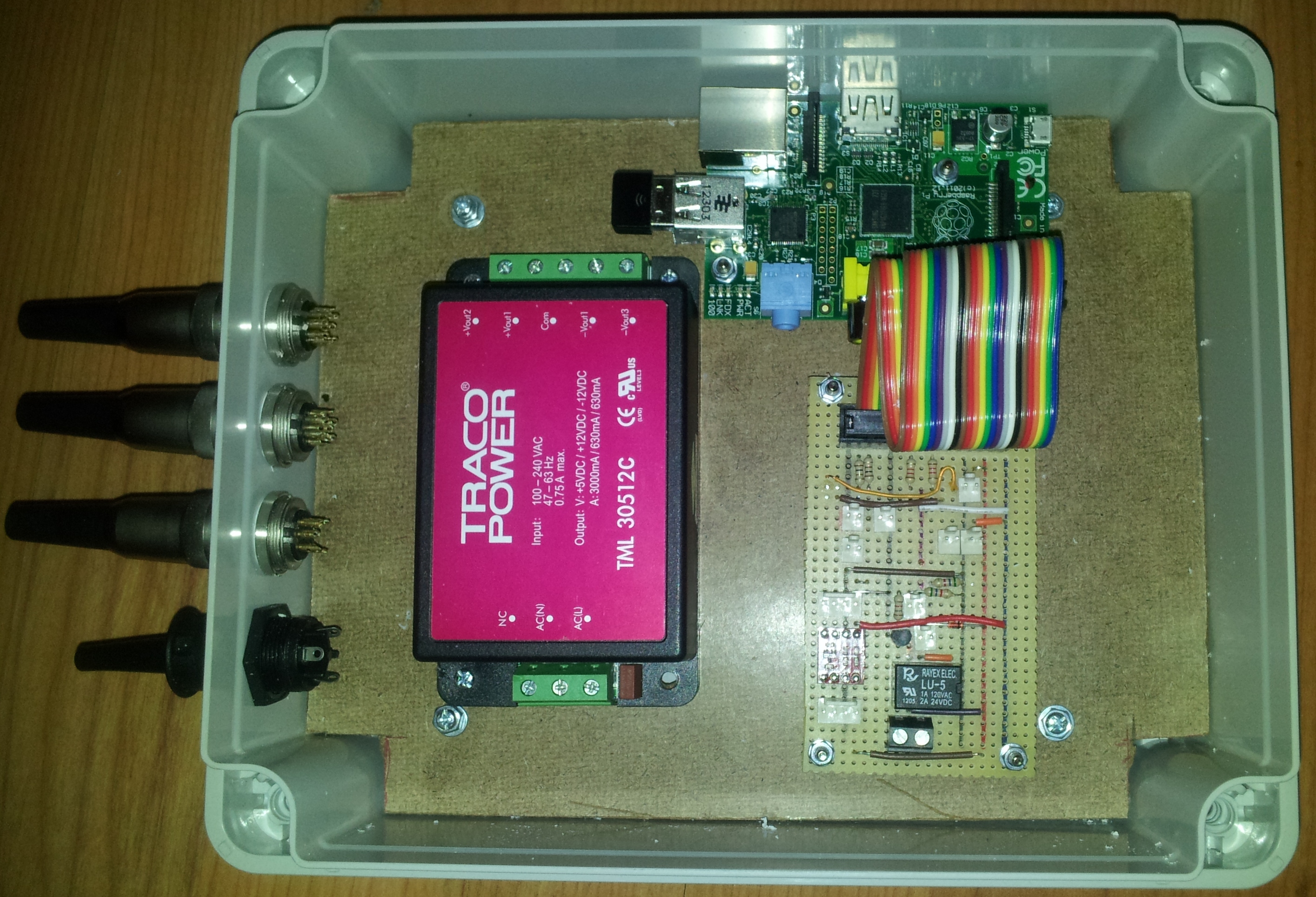
Note the small red circuit board - this is a level converter bought for £1.50 online, allowing me to run the RFID board at 5v without grying the 3.3v UART of the RaspberryPi. The reader would run at 3.3v, but with slightly reduced range
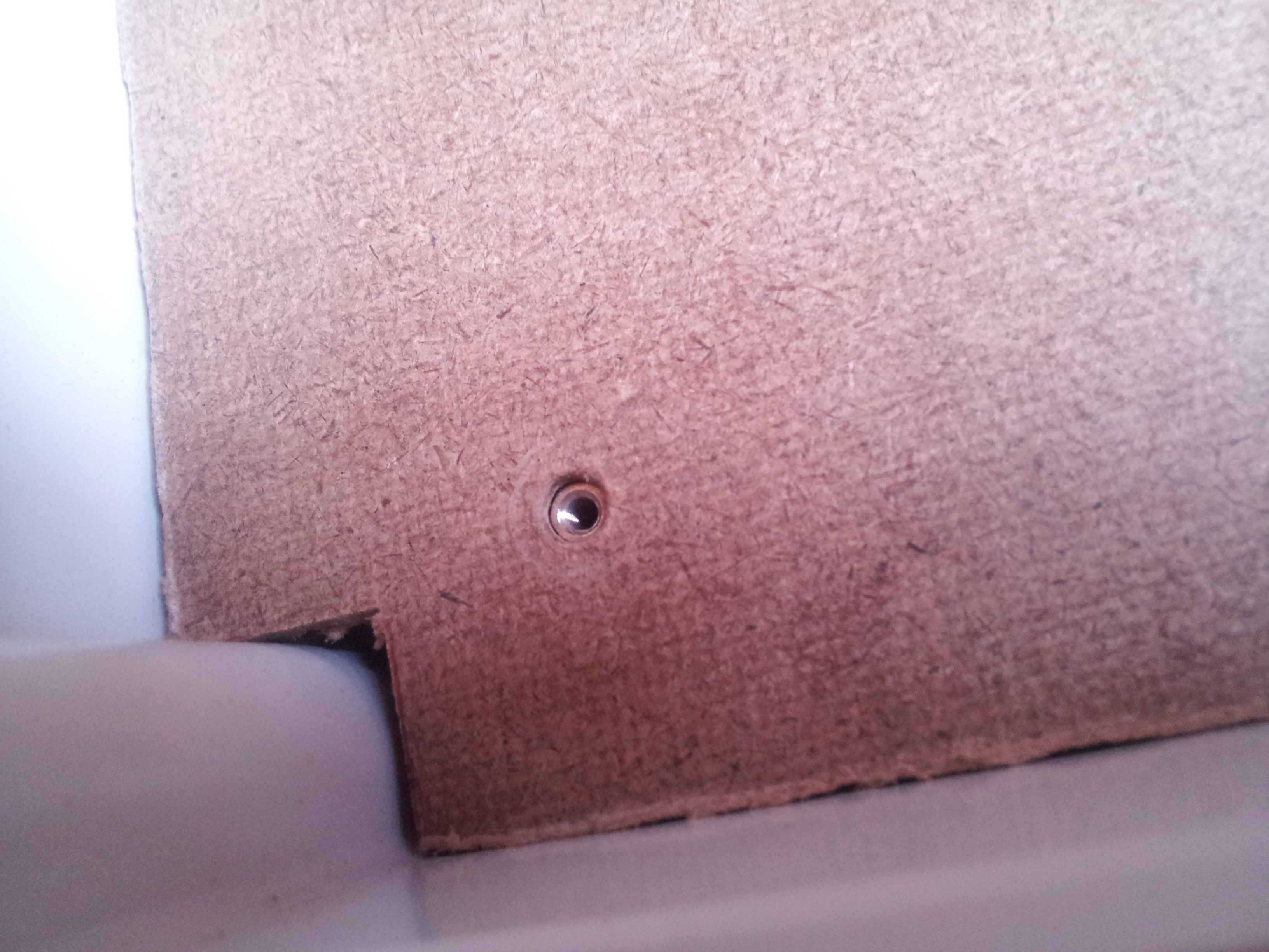
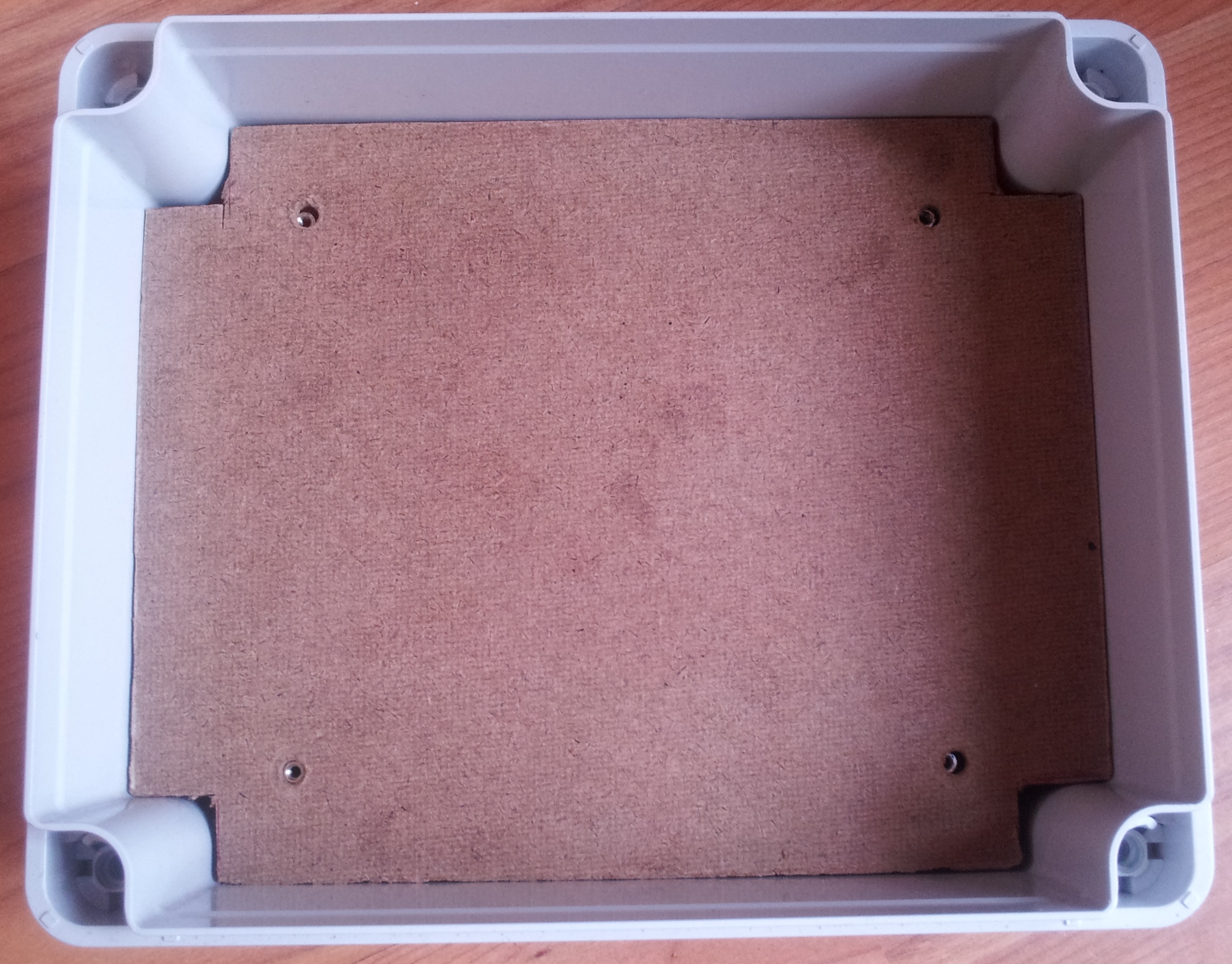
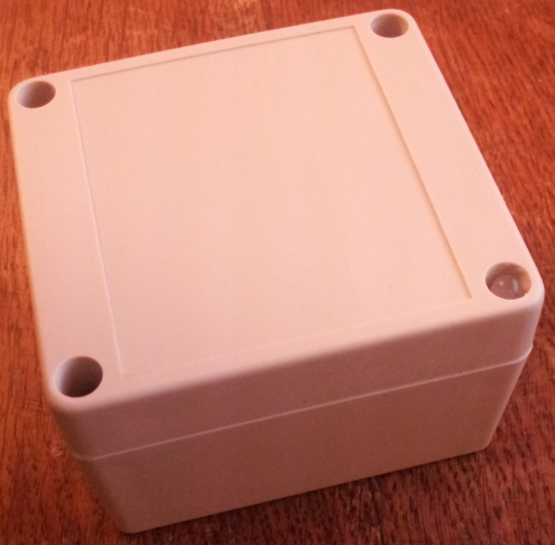
Finding an enclosure
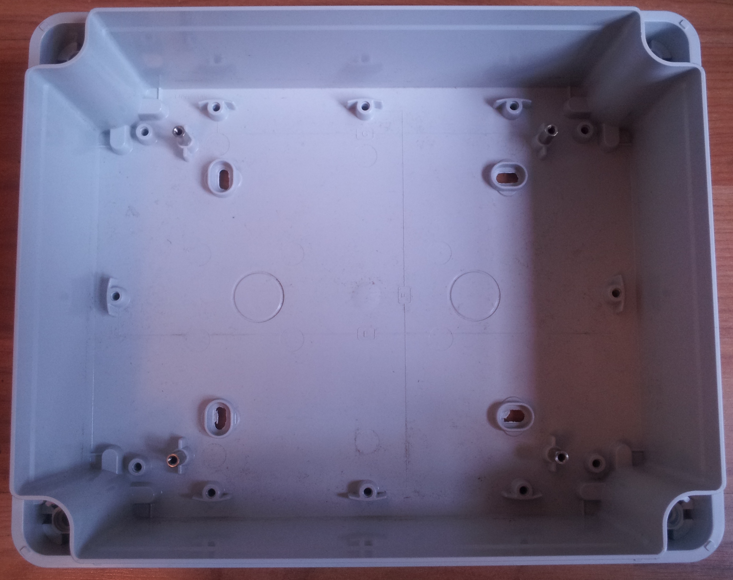
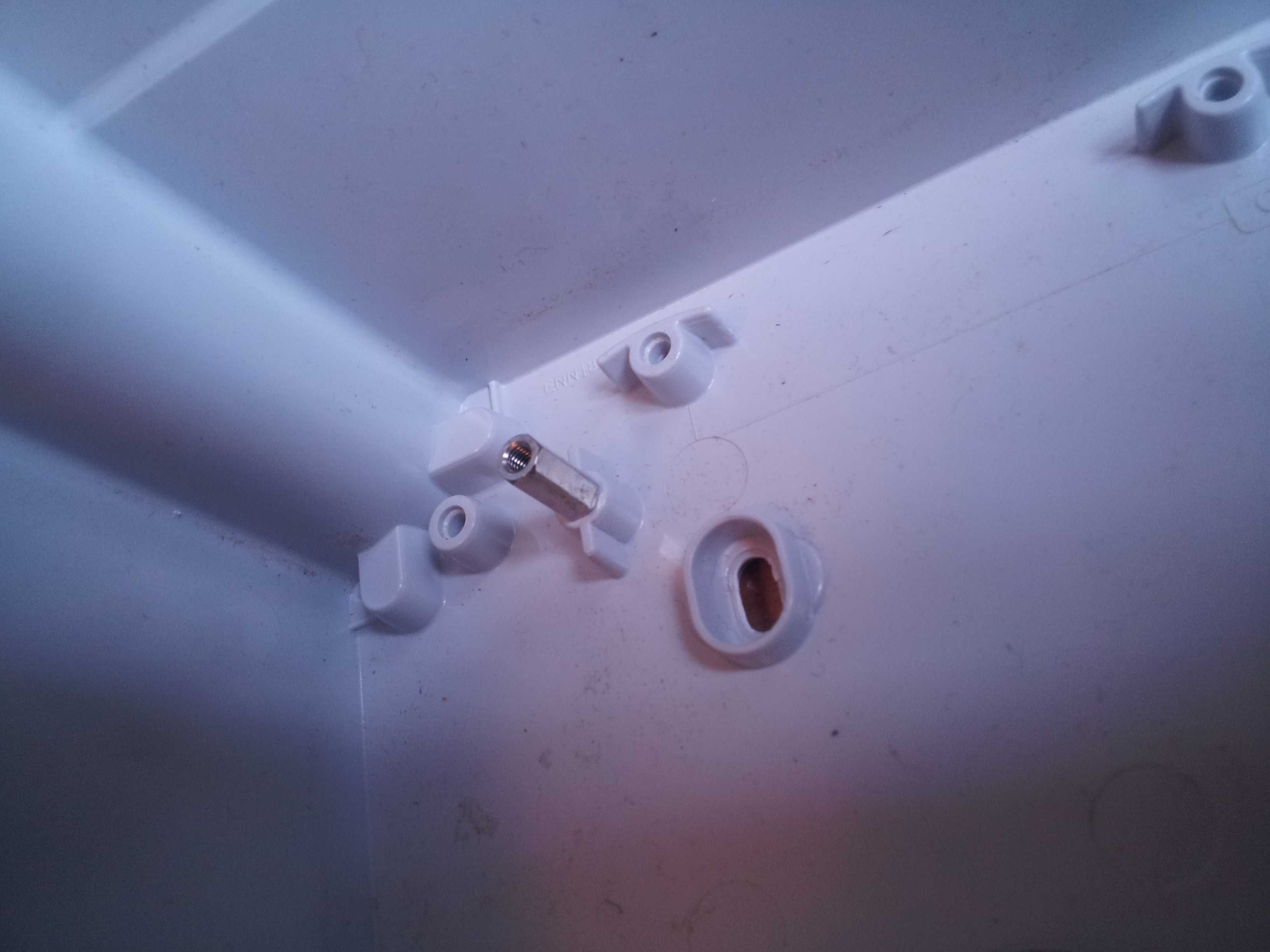
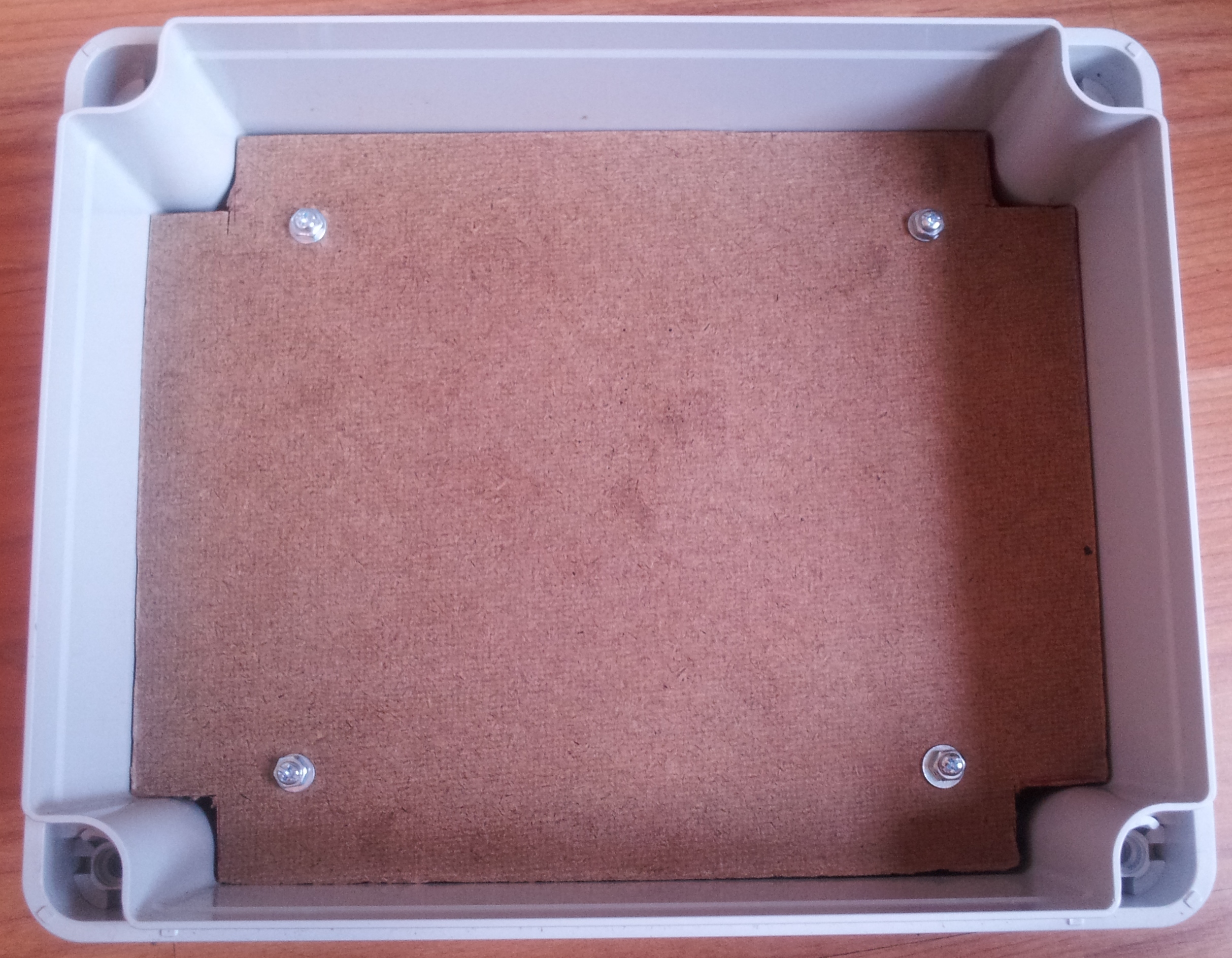
Stand-offs installed to mount the backing board to
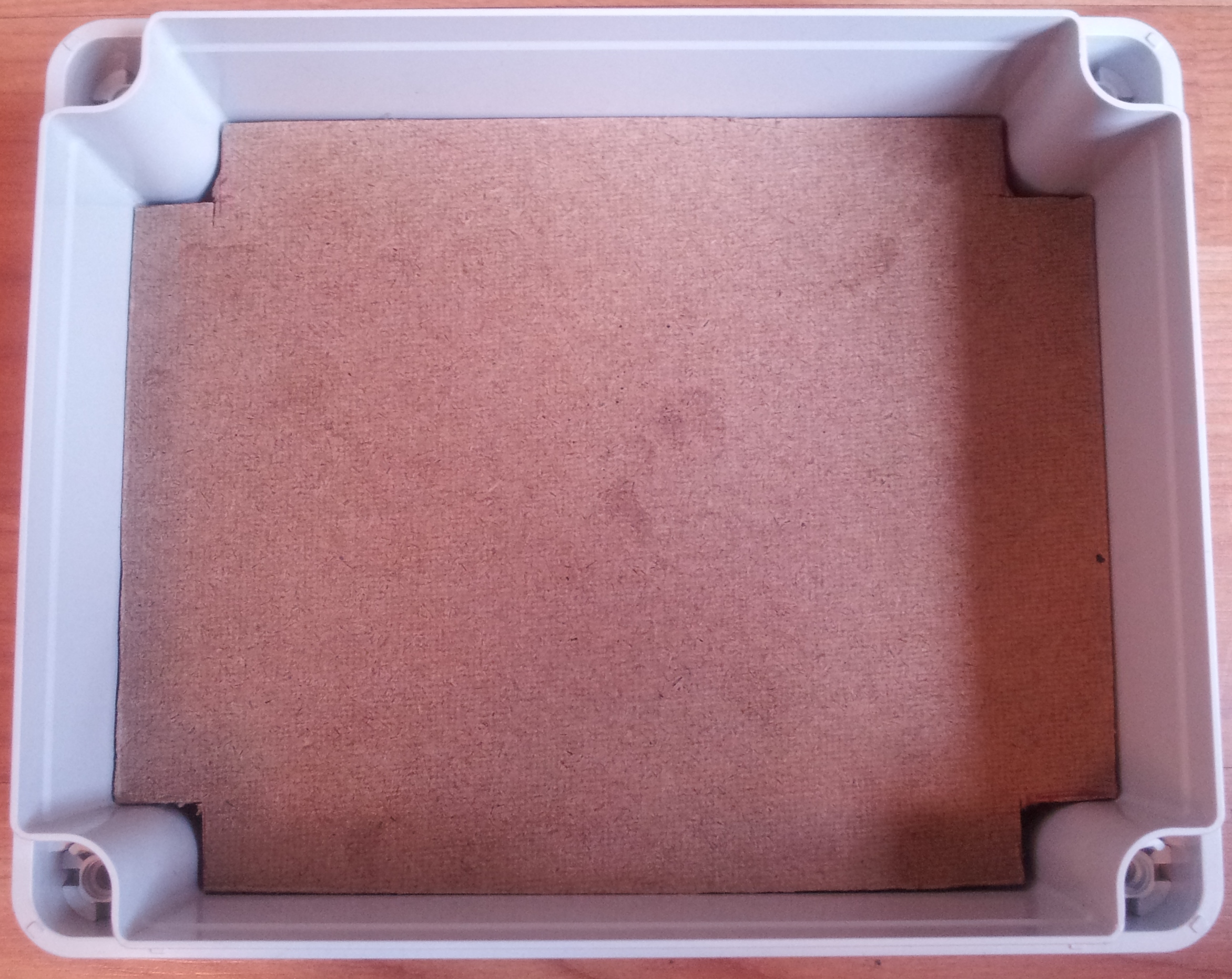
Making a backing board
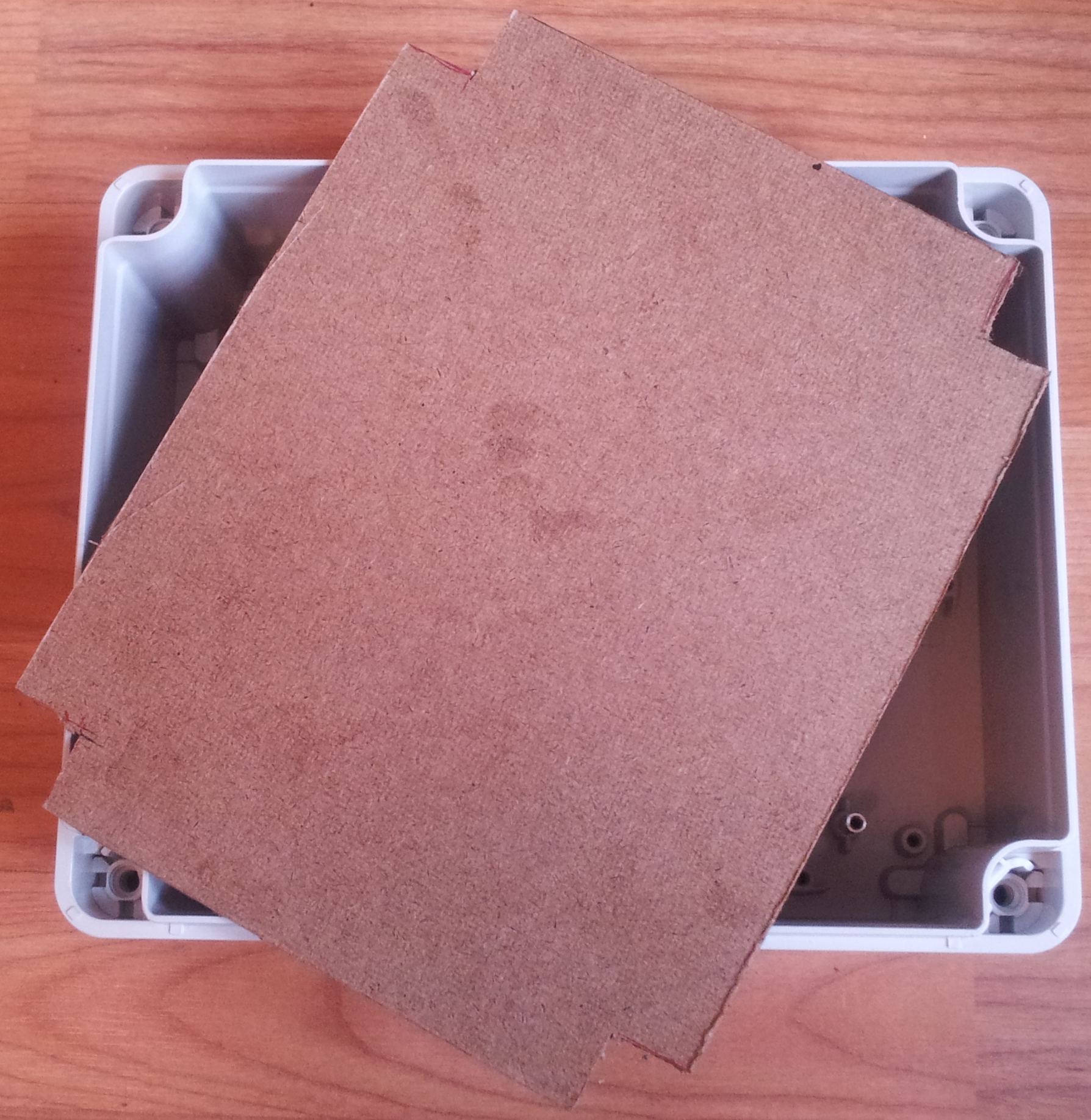
The backing board. Securing all kit to this makes mounting the box itself to a wall (if required) easier, since the whole board can be lifted out. I made mine from the mdf at the back of a cheap picture frame.
Getting the circuits ready

Laid out on the table ready for boxing up
Mounting in the box
Partially installed...
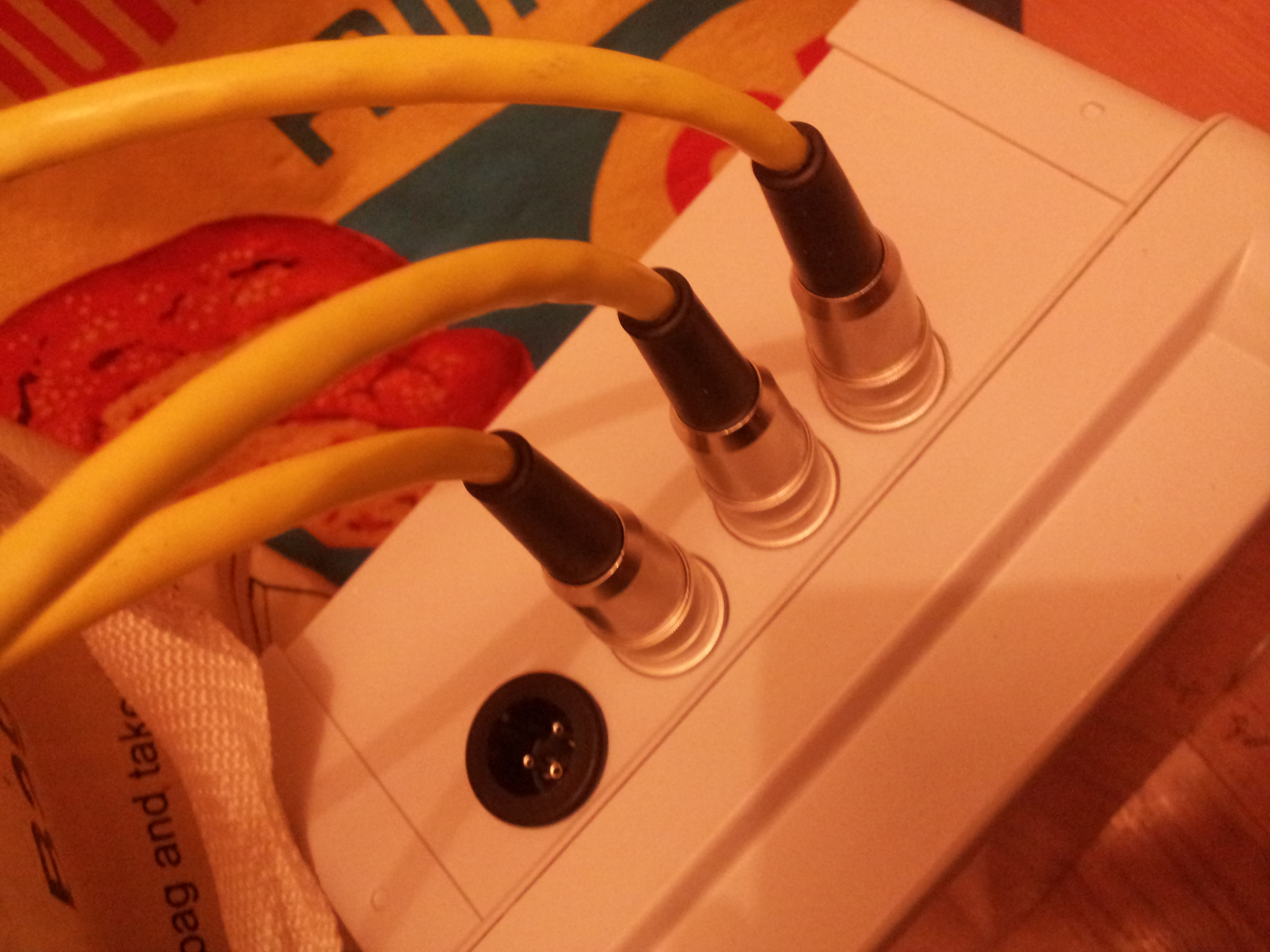
Holes for power and comms cut using a cone drill. DIN sockets with varying pin numbers were used for the maglock, button, and RFID reader respectively to ensure the correct connections are always made. Standard UTP (stranded) was used for the cabline, since it is easy to find
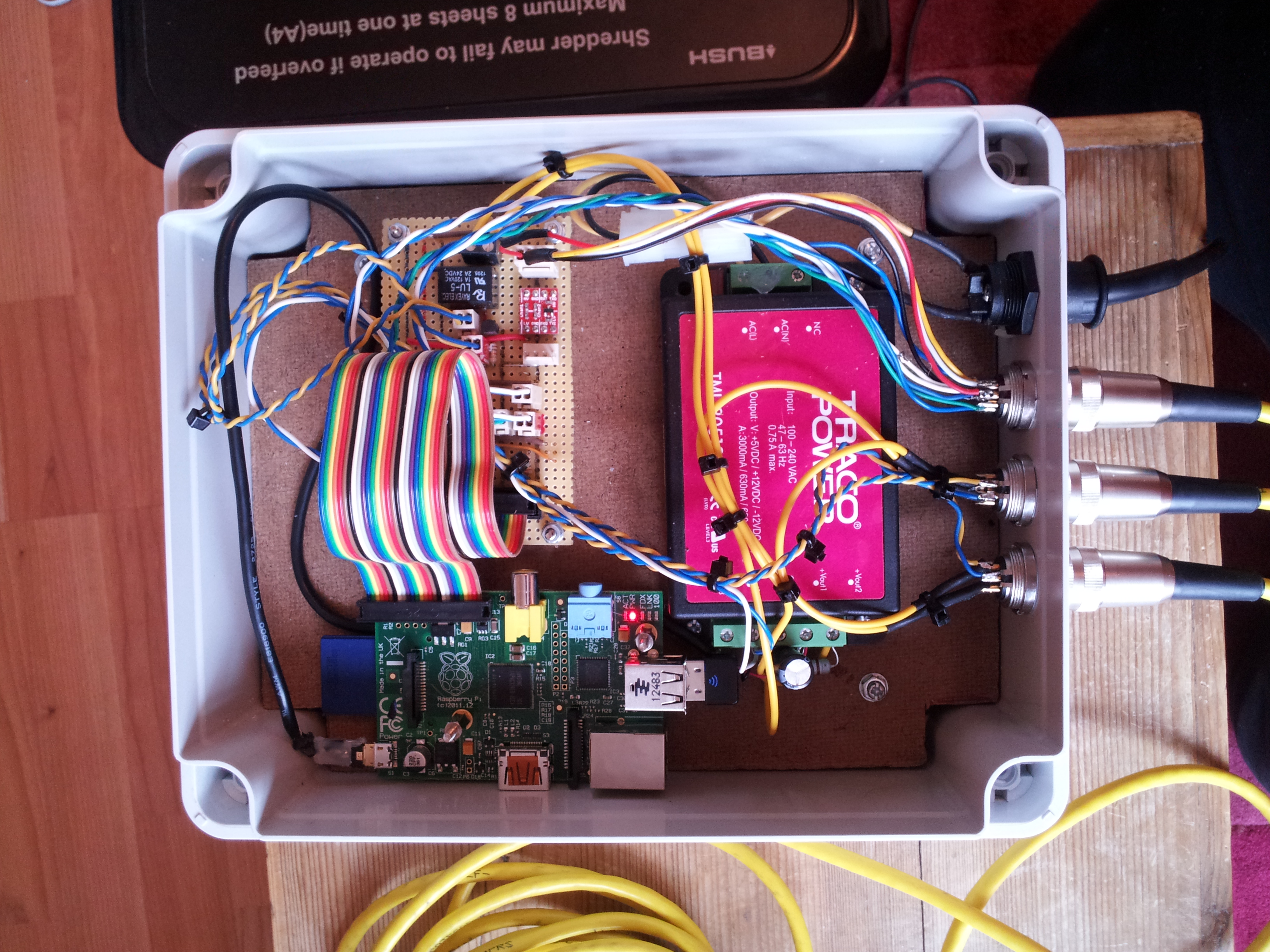
Fully installed. Note that powerto the pi is via the micro USB. Initially I powered the Pi via the GPIO 5v line, but this bypasses all voltage protection, and a killed a Pi that way. Seemed to make sense to use the 'proper' power connector after that!
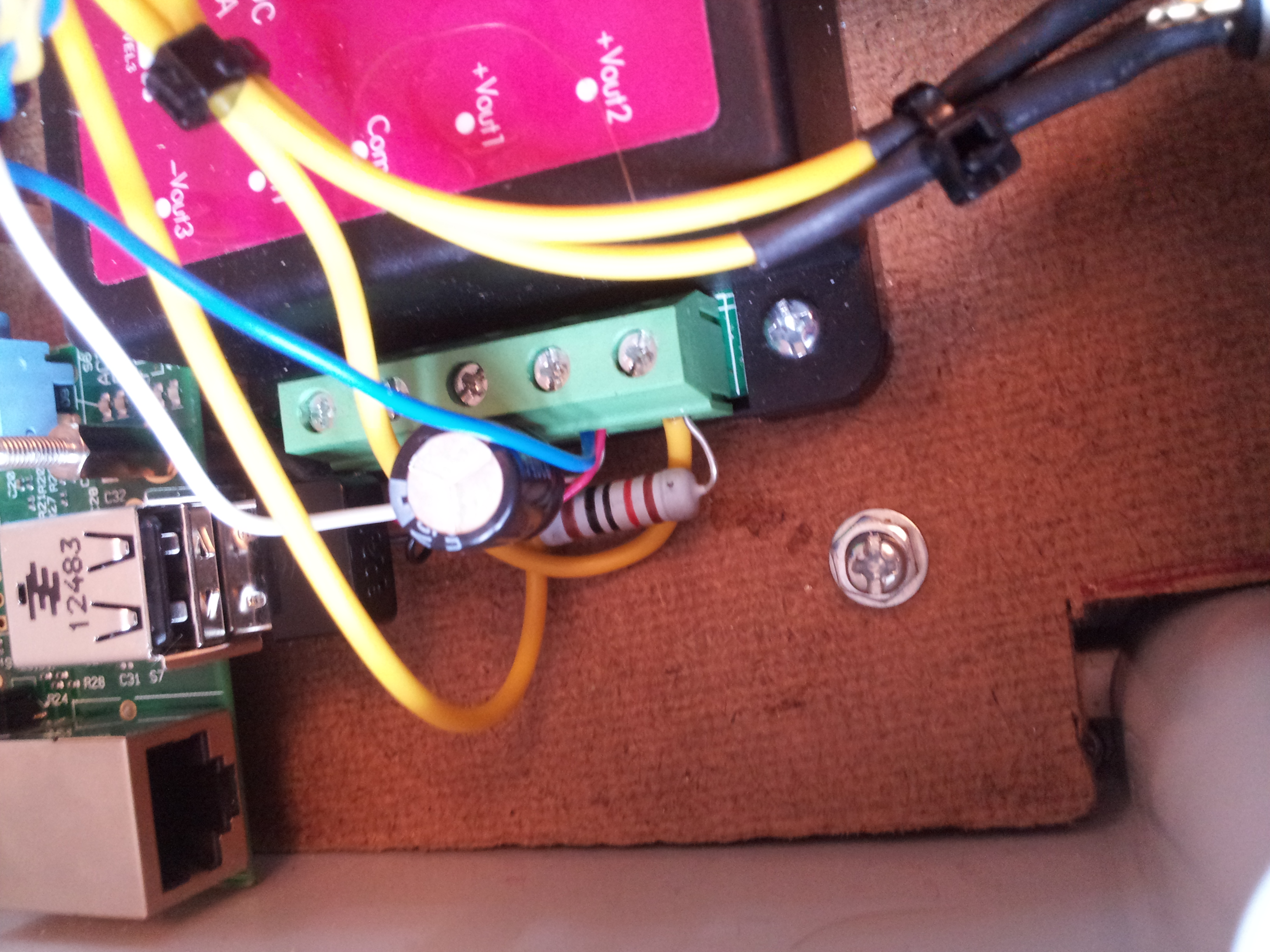
Note the 120 ohm load resistor across the 12v output. This is very important! According to the datasheet, the 5v regulation does not kick in on this SMPS until the 12v output is at 10% load. This means that if the maglock is not connected, then the 5v output can be up to 6.5v. I killed a raspberry PI this way!
Wiring up peripherals
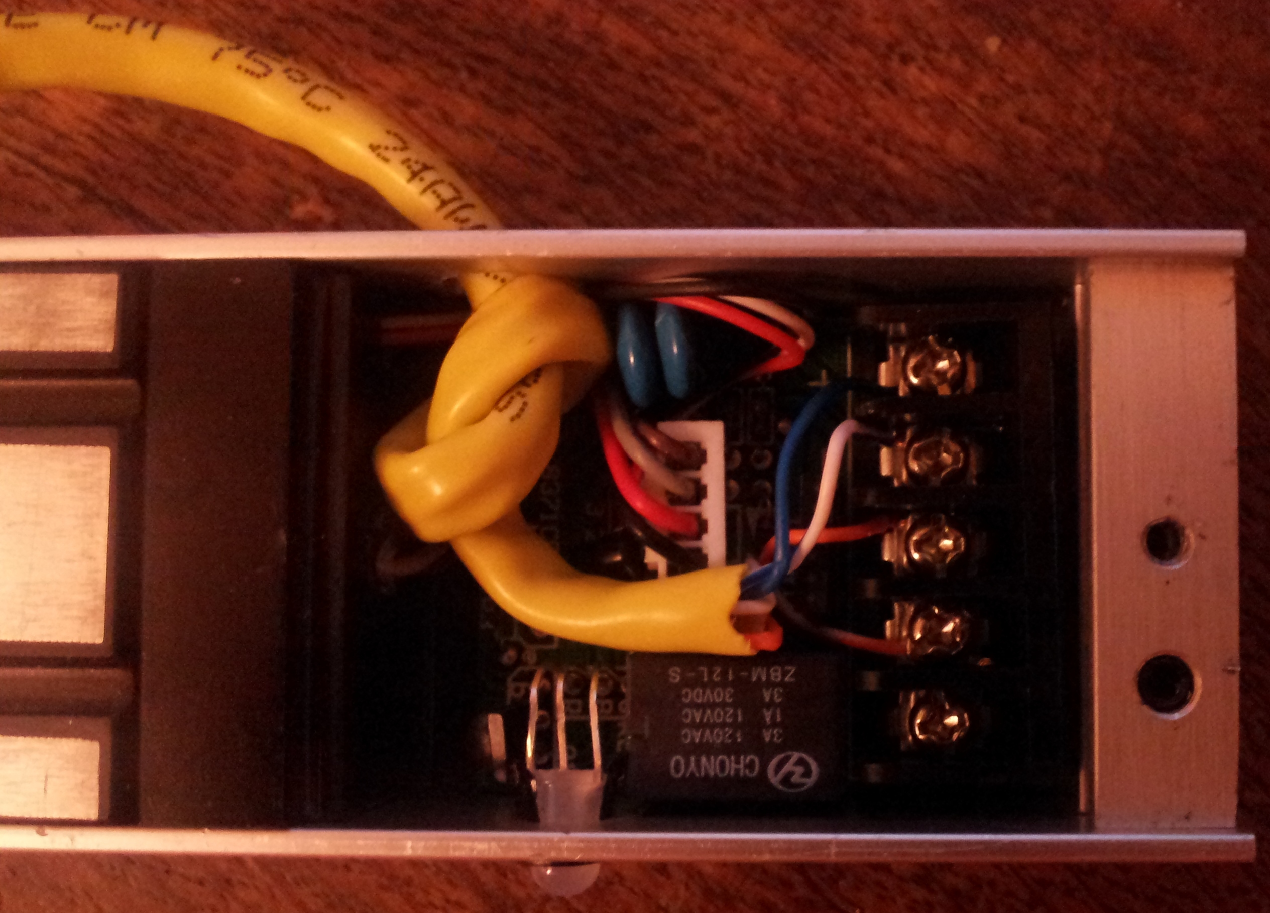
The maglock. This has a nominal 280kg holding force and draws ~450mA. It was bought on ebay for ~£30
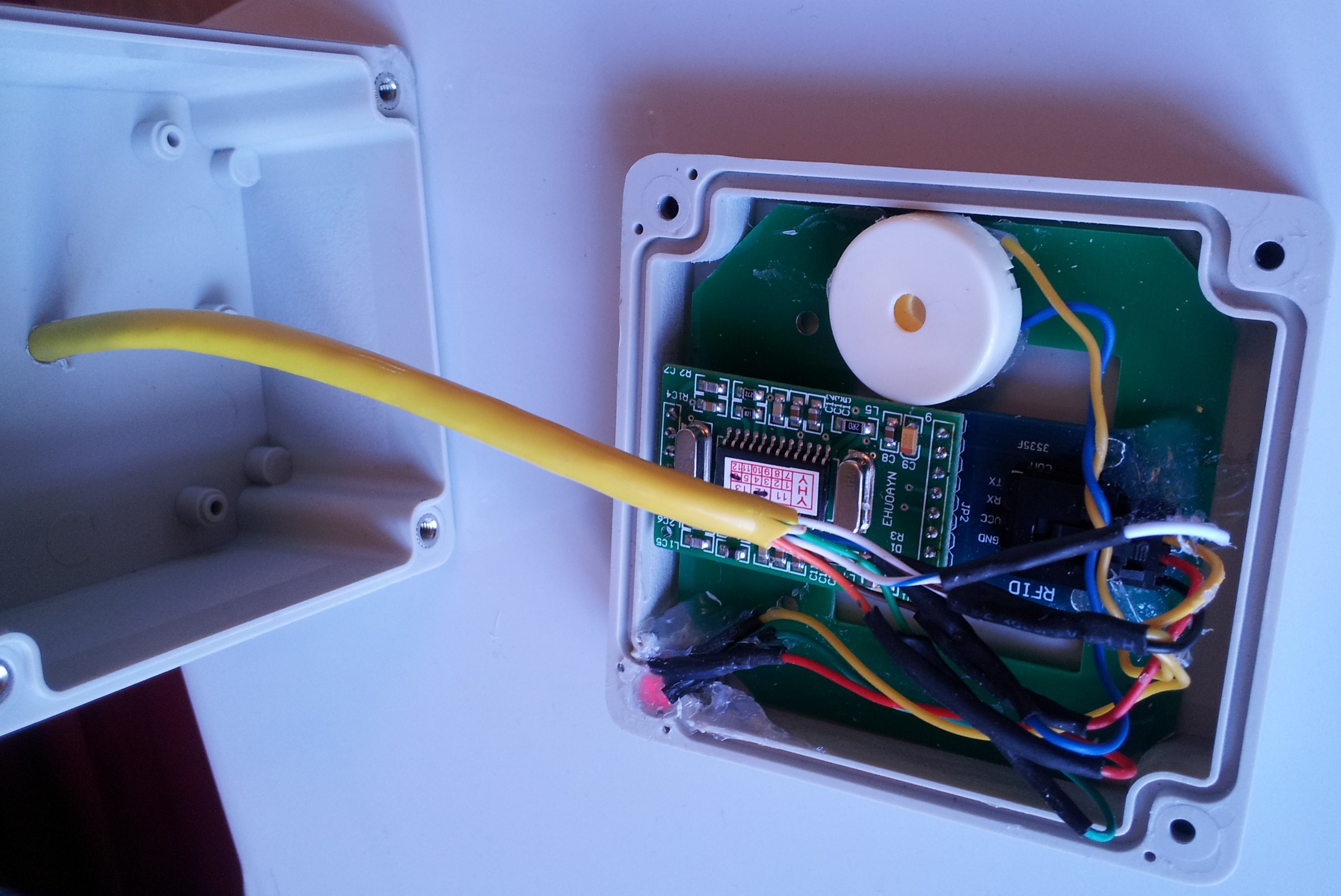
The internals of the RFID reader. The reader itself uses 5v or 3v TTL logic. I'm running it on 5v, as it gives slightly better range. However, the Pi uses 3,3v logic, which means some level conversion is required at the Pi end. The buzzer is also mounted here. Connections are:
- RX
- TX
- LED GREEN
- LED RED
- BUZZER
- COMMON
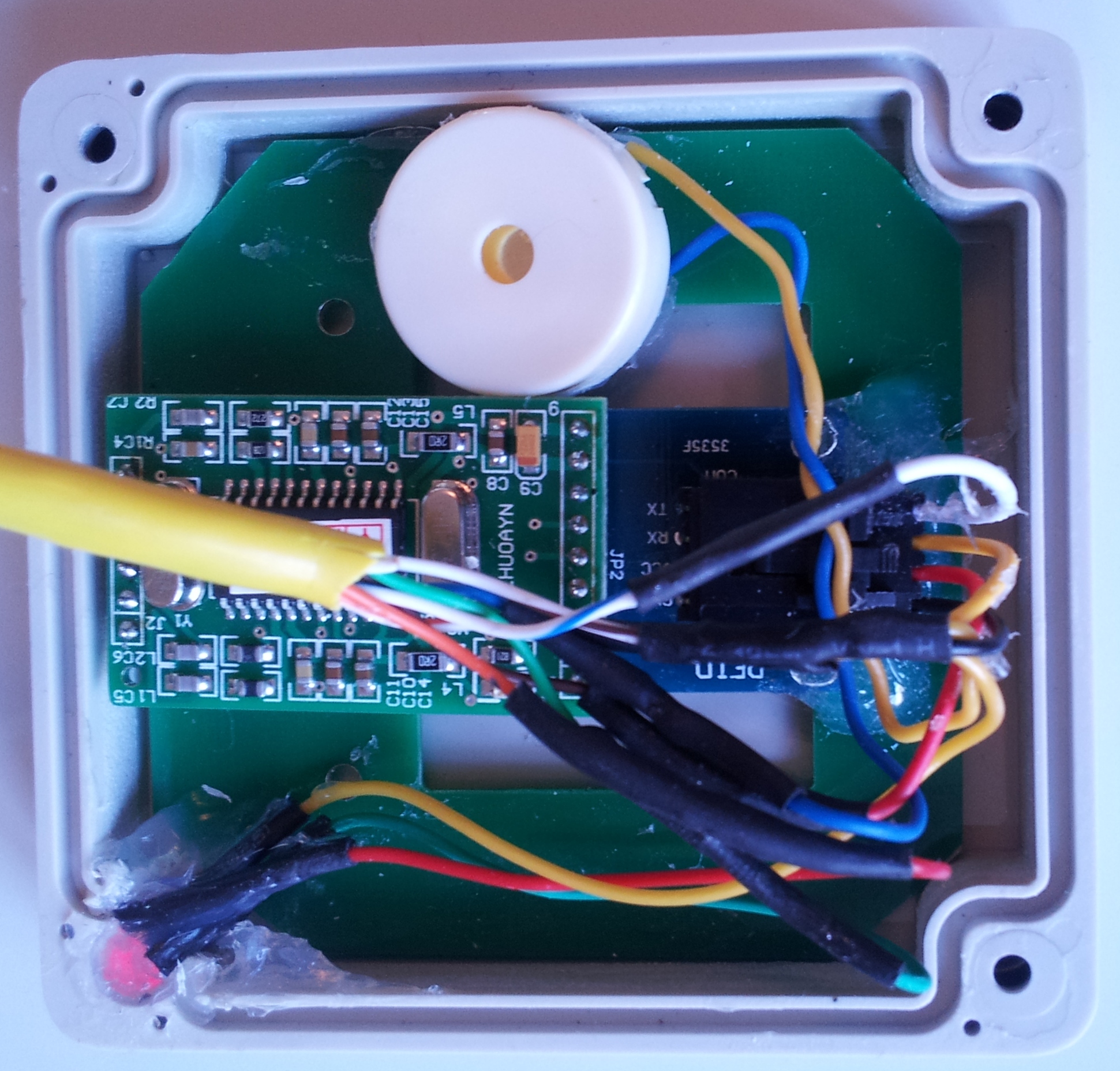
The box was from maplin, and was a perfect fit...after trimming the corners of the antennae board slightly. Luckily this was possible without impinging upon the tracks at all
The closed RFID reader. Box was from maplin for ~£5. One of the 4 lid screws has been replaced by a bicolour indicator LED
All done!
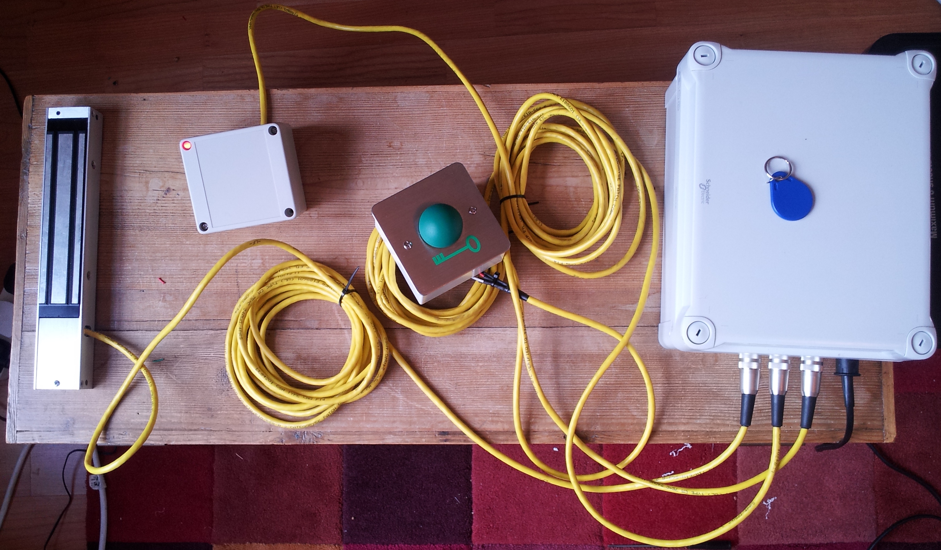
The assembled unit, ready for installation The push button directly interrupts power to the lock, ensuring that the system is fail-safe in the event of emergency. However, if the pi is functioning as normal, it will detect this press, and hold the lock open on button release for an additional few seconds. Thelock is held open for 5 seconds on swipe of a valid RFID card.